
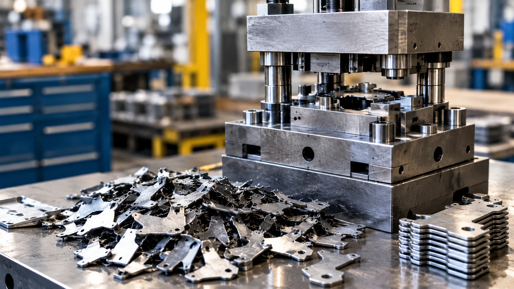
Some waste is built into machining before a single part is rejected. In aerospace, for example, buy-to-fly ratios of 10-to-1 are common, meaning only about 10% of the starting material ends up in the finished part. Other applications may not produce nearly as much waste, but every rejected part still adds to the loss.
What many teams overlook is that tooling-related scrap often traces back to design-stage decisions, not just shop-floor problems. Catching tooling design mistakes early is far cheaper than correcting them during production.
In this guide, we’ll break down 9 common tool and die design mistakes that can lead to scrap, along with practical fixes to support a more effective scrap reduction strategy from the start.
Mistake #1: Ignoring Material Behavior and Properties
Designing a die without accounting for metal behavior can lead to out-of-spec parts and avoidable scrap.
How to fix it:
- Factor material properties into your stamping die design from the very start.
- Compensate for material springback based on the specific grade and thickness being formed.
- Consider material selection alongside grade, thickness, and forming requirements before finalizing the tooling design.
- Verify the material grade and certifications, and review available forming limits before finalizing the tooling design.
- Run a forming simulation for complex parts to evaluate material behavior and identify potential thinning, cracking, wrinkling, or springback issues early.
Mistake #2: Incorrect Punch-to-Die Clearances
Too much clearance can produce heavy burrs, excessive rollover, and inconsistent hole sizes that compromise stamping accuracy.
How to fix it:
- Follow die clearance guidelines for the specific material and thickness, typically expressed as a percentage of stock thickness.
- Adjust punch and die clearance based on material strength, thickness, and characteristics such as coatings.
- Inspect and measure clearances during die tryout to confirm the tooling is performing as designed.
- Monitor burr height during production as an early indicator of clearance or punch wear and an opportunity for burr reduction.
Mistake #3: Skipping Tolerance Stack-Up Analysis
At the same time, over-tolerancing adds unnecessary cost and can raise scrap risk when tight tolerances aren’t actually required.
How to fix it:
- Analyze tolerance stack-up across the tooling and the finished part’s functional dimensions.
- Tighten tolerances only where the part’s function truly requires it.
- Use GD&T, following the ASME Y14.5 standard, to communicate dimensional and geometric requirements clearly and support design for manufacturability.
- Confirm critical tolerances against your customer’s assembly and functional requirements.
Mistake #4: Poor Part Location and Alignment Features
Poor locating features can create defects that repeat throughout production, while persistent misalignment can lead to uneven wear and shortened tool life.
How to fix it:
- Size pilots to provide a reliable fit without excessive clearance or interference.
- Position pilots where they can provide stable strip location without interfering with critical part features.
- Design dependable locating points into your progressive die design to maintain consistent tooling alignment.
- Check pilot location during regular tooling inspections and replace worn components before they cause positioning errors or dimensional drift.
Mistake #5: Wrong Tool Steel or Heat Treatment
Heat treatment can also cause dimensional changes or produce hardness outside the specified range, affecting critical features and tool hardness requirements.
How to fix it:
- Match tool steel selection to the material being formed, tooling application, and expected production volume.
- Specify heat treatment requirements clearly on the relevant tooling drawings and specifications.
- Allow for finish grinding after heat treatment when dimensional requirements call for it.
- Consider coatings for improved wear resistance in high-wear applications and to help extend tool lifespan.
Mistake #6: Neglecting Slug Ejection and Die Protection
Reliable slug ejection and effective die protection are therefore important for stable production.
How to fix it:
- Design adequate clearance and provide a reliable path for slug evacuation in your progressive die design.
- Evaluate die venting where trapped air could affect a specific forming operation or part feature.
- Use appropriate shear angles, slug retention features, or surface treatments where needed to control slug movement.
- Add sensors and other die protection measures where misfeeds, double hits, or slug-related failures could damage the tooling.
Mistake #7: Overlooking Strip Layout and Material Flow
These forming defects may not become obvious until the tool is already running in production, making them more expensive and time-consuming to correct.
How to fix it:
- Develop multiple progressive die layout options and compare material utilization, part quality, and strip stability.
- Review the progression sequence to establish a logical forming order.
- Leave adequate material for carriers and tie bars while maintaining reliable strip support.
- Evaluate material flow and movement carefully during the design stage to identify potential forming issues early.
Mistake #8: Designing Without Press and Feed Compatibility
Mismatches between the tooling and equipment can lead to crashes, misfeeds, inconsistent part quality, and unnecessary setup adjustments.
How to fix it:
- Confirm press specifications and tonnage requirements before you start the tooling design.
- Design the feed pitch and pilot timing to work with the feeder and press cycle.
- Build in adjustability where practical, such as shims and adjustable stops.
- Communicate early with production to confirm press capabilities, feeder requirements, and setup constraints.
Mistake #9: Skipping Simulation, Prototyping, and Tryout
How to fix it:
- Run forming simulation on complex or high-risk parts before committing to final tooling.
- Build prototype tooling and first article inspection into the validation process where the application warrants it.
- Prepare a die tryout checklist covering key dimensions, part quality, and cycle behavior.
- Document adjustments and findings during process validation for future production runs and tooling improvements.
Design Out Scrap Before It Starts
Review your current tooling for the warning signs covered in this guide, from material behavior and clearances to strip layout, press compatibility, and die tryout. If you need an experienced review, H&H Tool & Die can help evaluate your tooling design and scrap reduction goals.
Contact us to discuss your tooling requirements or schedule a design review.