
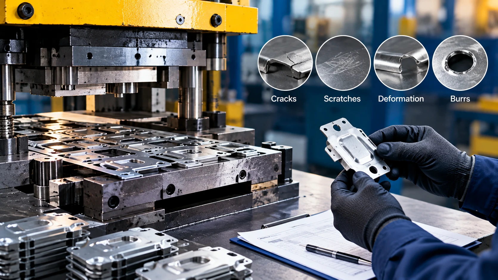
Even the best-run stamping operations can bump into quality challenges like this. Presses drift, tooling wears, and material lots vary. Metal stamping defects show up in nearly every process at some point, and your production costs climb fast when they sneak past inspection.
What separates a minor hiccup from a costly recall is early identification and honest root cause analysis. This guide walks you through a step-by-step method for stamping quality control, covering how to spot defects, what causes them, and how to keep them from coming back.
Step #1: Understand Where Defects Usually Come From
Your operators, die setters, and quality inspectors may catch different clues on the floor. When you track defect history across shifts, those observations turn into clear patterns. Documenting every issue by die number, material lot, and shift helps you connect tooling wear and other production variables.
Step #2: Identify Burrs and Edge Quality Problems
To check, run a gloved finger along the cut edges and use magnification for a closer look at fine features. Burrs usually come from dull punches or incorrect punch and die clearance for the material being run.
To prevent burrs in stamping, you should:
- Keep your tooling sharp on a set sharpening schedule.
- Verify that your clearance settings match the material type and thickness in the job.
- Flag recurring burr issues to die maintenance instead of deburring around them.
Maintaining tooling sharpness and correct clearance solves most edge quality problems at the source.
Step #3: Recognize Cracking and Splitting
Inspect these areas closely during first article checks and again during in-process inspection. Usually, metal cracking occurs when material is stretched past its forming limit or the wrong material grade is selected for the part geometry.
To avoid this issue, you should:
- Match material ductility and grade to the part geometry before tooling is cut.
- Adjust blank size and die radii to ease stress concentration in tight corners.
- Consider material conditioning for trickier forming applications.
Designing around known forming limits helps you spot most splitting defects before you ever stamp the first part.
Step #4: Detect Wrinkling and Material Buckling
Compare your finished parts against approved samples and inspect by both sight and touch. Wrinkling defects usually go back to blank holder pressure that’s set wrong, or compressive force that outpaces the material’s resistance.
Here’s what you can do:
- Adjust blank holder force to control how material flows into the die during deep drawing.
- Review draw bead design for deep draw and flanging operations.
- Check lubricant distribution, since uneven coverage creates uneven material flow.
Small pressure and lubrication adjustments usually clear up wrinkling without touching the tool.
Step #5: Check for Springback and Dimensional Variation
Measure your bend angles with gauges or CMM equipment and track your results across the full run. Material type, thickness, and bend radius often drive springback and determine how much elastic recovery you’ll see.
You should:
- Over-bend dies to compensate for predictable springback.
- Use bottoming or coining when bends need to hold tighter tolerances.
- Test material when switching suppliers or lots, since properties shift between sources.
Tracking bend angle accuracy over time helps you catch dimensional variation before a whole batch drifts out of print.
Step #6: Inspect for Surface Scratches and Galling
Inspect parts under proper lighting against a clear finish standard. Inadequate lubrication or worn die surfaces usually lead to surface scratches and galling. They are especially common when running stainless steel.
To prevent these problems, you should:
- Apply the right lubricant for the specific material in the job.
- Keep die surfaces maintained and free of buildup.
- Schedule regular polishing for dies running cosmetic parts.
Managing lubrication and die wear keeps surface finish consistent across long runs.
Step #7: Look for Misalignment and Incomplete Forming
Inspect witness lines and alignment marks, then measure critical features against the print. Worn guide pins, poor strip positioning, or low press tonnage can frequently lead to stamping misalignment.
To fix these issues, you must:
- Inspect and replace guide pins and bushings on a regular schedule.
- Confirm press tonnage matches material thickness and part geometry before the run starts.
- Verify strip feed settings and pilot pin condition at setup.
Step #8: Monitor Tooling Condition and Track Defects Over Time
Log your tool hit counts against expected tool life, and inspect for wear patterns or chipping during scheduled checks. Keep defect records linked to specific dies, materials, and production runs so patterns show up sooner, not after scrap piles up.
Generally, tooling companies with in-house die setting and maintenance tend to catch this drift sooner than those that outsource the work. In-house die setting shortens the loop between spotting your problem and fixing the tool. Additionally, include full die repair history in your defect tracking system so every correction is documented for the next run.
Take Control of Your Stamping Quality from Day One
Need tooling support or planning a new stamping project? H&H Inc. is here to help you. We specialize in tooling design and have 20 years of experience in the oil and gas industry. Our facility can produce one to ten million parts.
Contact us today to discuss your next tooling project.